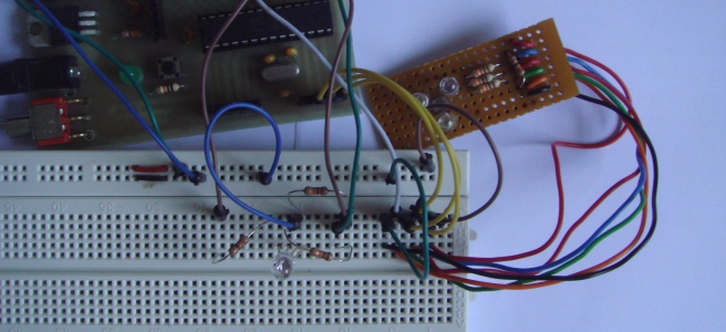
Previously I have made a colour sensor using Arduino but don’t have the time to update it on my blog. Today I am going to share the details of this mini project. Basically, the sensor consists of three LEDs and Light Dependent Resistor (LDR). The LDR will detect the colour and display it to another RGB LED. Besides display it on the RGB LED, the colour will also display on PC. RGB LED is commonly used in display colours on LCD or OLED such as the monitor and television.

There are actually many methods to detect colour, but using only LED and LDR should be the cheapest way to do this job. Let me explain how this sensor works. First, the LDR has to detect the contrast between black and white surface. To detect the colour, each LED takes turn to shine onto the surface and the Arduino will read the voltage on LDR.

I made the colour sensor on a piece of strip board. It consists of 3 colour LEDs, which is red, green and blue and also a Light Dependent Resistor (LDR).


After having the contrast in black and white, now the LDR is ready to detect different colour surface. Again, the three LED, Red, Green and Blue will take turn and shine on the surface. Next, Arduino will read the voltage on LDR and do some calculations to get the colour value.
Finally, we will use the colour value to display it on another RGB LED. The output RGB LED requires Pulse Width Modulation (PWM) pin on the Arduino. Since the PWM output on Arduino is 8 bit, this gives us 8 bit resolution, 255 steps on each colour. As mentioned before, the output is also displayed on the PC. Arduino will communicate with the PC through serial communication and pass the colour value to Processing. Some calculations will be done on Processing and display the colour on PC.
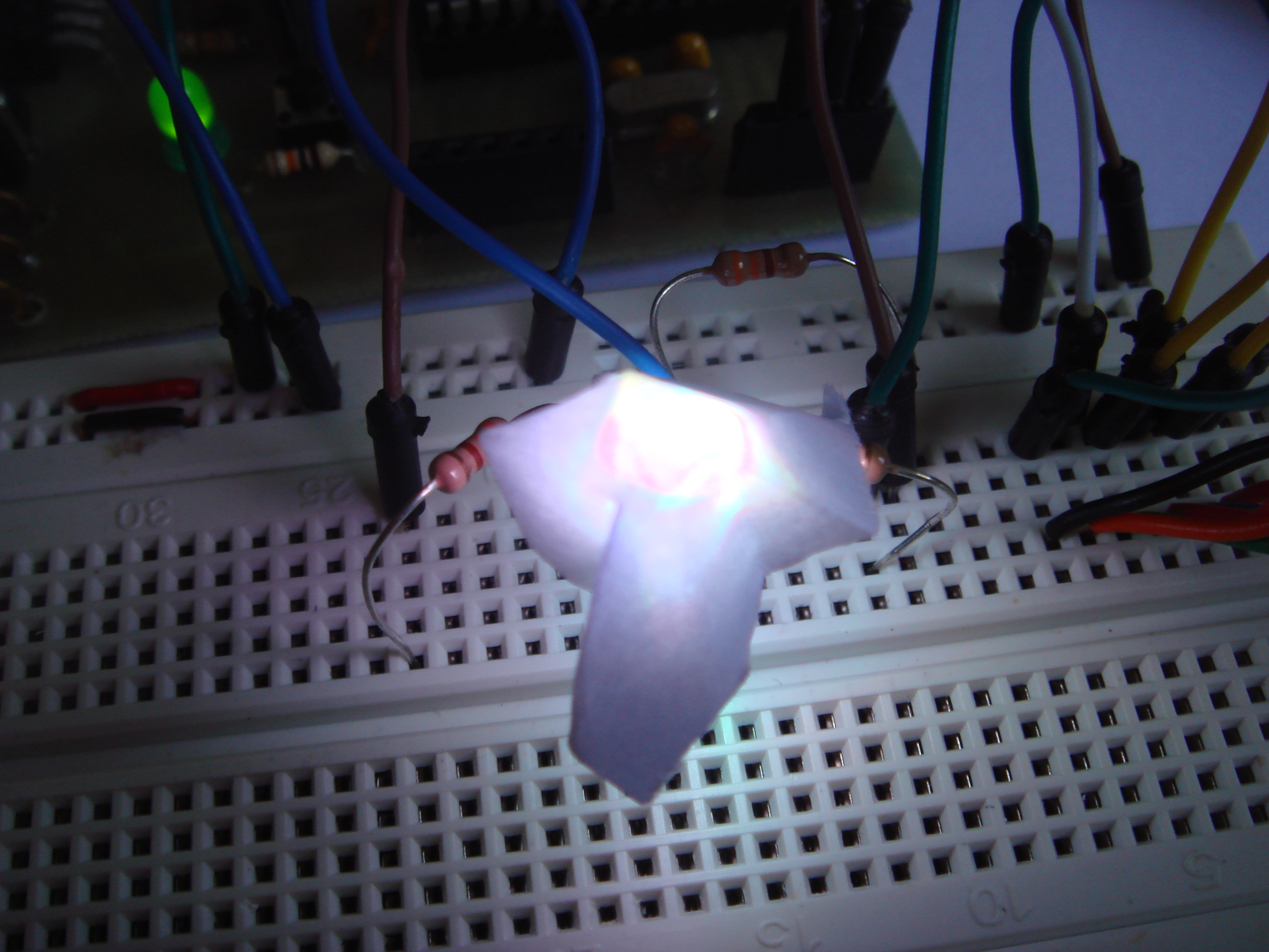
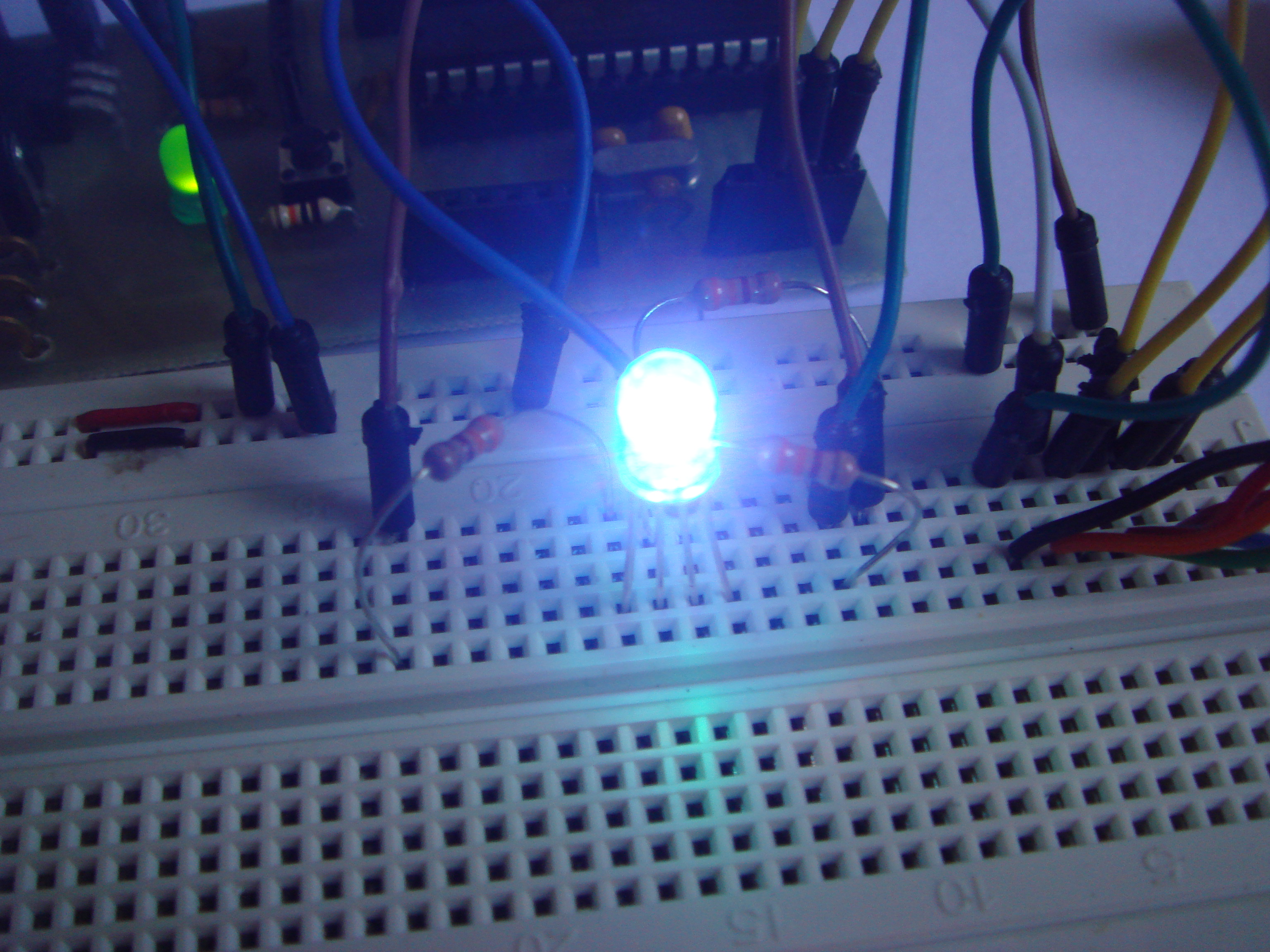
Some images on the output RGB LED. Note that I am using a clear RGB LED, so to have a better display on LED, I put a piece of paper covering the LED to diffuse the light.

Finally, a video on this colour sensor. Enjoy 😀

It’s better to have collimator put on the light-sensor to avoid it being saturated (or adding extra value) by side light from LED. Try it and you’ll see the color replication will be much more precise.
Thanks Bohdan for the suggestion. What is a collimator?
Collimator is a simple optical device which limits amount of light or directions from which this light could reach optical sensor or eye.
In your project it could be just simple opaque tube put on the sensor.
On the picture below you can understand why it can help.
Left side is w/o collimator – sensor receives not only light reflected from object (which color you want to replicate) but also from LEDs on sides from sensor.
On right side of picture there is collimator-tube used, preventing sensor to be affected by “false” light from LEDs, so receiving it only from object.
Reference :
http://www.instructables.com/id/Using-an-RGB-LED-to-Detect-Colours/
You guys can try it out !
Thank you.
Thanks for the reference.
this project is awesome. I want to replicate this project but I’m a beginner (I start last week 😉 ) I have an Arduino UNO can you explain to me (baby steps) if I only need to connect the Arduino to my PC and then do the wiring as the photo or I need to program something or do something on the arduino software? there is a way to use something else instead the arduino? I want to know if this can be portable and cheap . thanks
Hi Lobo, if you would like to start out using Arduino, I would suggest you to familiarize with basic inputs (buttons) and outputs (LED) and the Arduino environment.
You need to program the Arduino for it to works. Some electronics knowledge would be helpful to you too.
Good luck and hope it helps.